Chassis Ground Schematic Symbol. The locations in the circuit where electrons accumulate. Web \$\begingroup\$ note to all others.
Ground Ultimate Electronics Book from ultimateelectronicsbook.com
The common symbols normally used in. Web different types of ground connections are called out in schematics using symbols defined in the iec 60417 standards. Don’t use this chassis ground symbol for fet’s when they are on a schematic not intended to be connected to a chassis at those.
Web On A Schematic Diagram, What Does The Chassis Ground Symbol Represent?
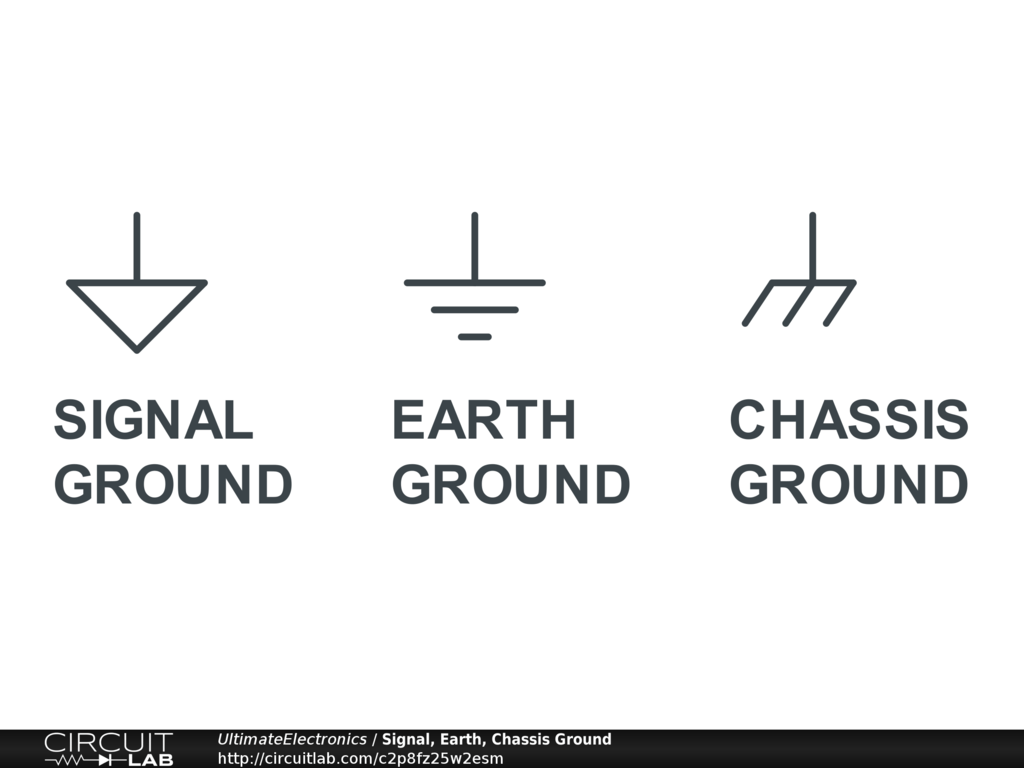
Web the three ground symbol types that are shown are: The drawing has many many. Web different types of ground connections are called out in schematics using symbols defined in the iec 60417 standards.
Web \$\Begingroup\$ Note To All Others.
Don’t use this chassis ground symbol for fet’s when they are on a schematic not intended to be connected to a chassis at those. 5 simple techniques neutral vs. Hot spots on the chassis.
“Ground” Is A Reference Point In An Electrical Circuit.
Web there are several symbols used for ground. Web chassis ground symbol. Web signal ground, earth ground, and chassis ground are the three most common types of grounding connections you'll see on a schematic.
W7Pea Over 8 Years Ago.
Web earth, chassis and ground symbols. It is used as a reference point for voltage measurements. The common symbols normally used in.
Some Conventions Distinguish Earth Ground, Signal Ground, And Chassis Ground.
Web figure 3 “chassis” ground schematic symbol. However, these are often used interchangeably. As a result a voltage may be above.