Ir2110 Inverter Circuit Diagram. Ir2110 inverter schematic 1n 4148 zener diode diode ln4148 full bridge ir2110 ir2110 full bridge. Web ir2110 inverter circuit diagram.
inverter IR2110 Open Collector Output Problem Electrical from electronics.stackexchange.com
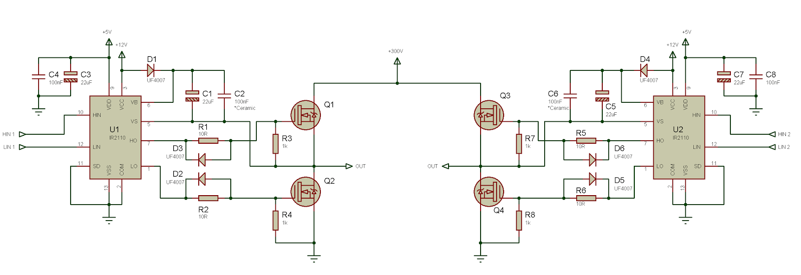
Figure 3 is a schematic illustration of the ir2110 inverter. The floating channel used to drive the n. Mofet driver 1r2210 is used to driver low side mosfets connected to center tapped iron core transformer.
Mofet Driver 1R2210 Is Used To Driver Low Side Mosfets Connected To Center Tapped Iron Core Transformer.
Web full h bridge and driver circuits scientific diagram. Ir2110 inverter schematic 1n 4148 zener diode diode ln4148 full bridge ir2110 ir2110 full bridge. Web download scientific diagram | ir2110 drive circuit from publication:
Web 2.1.2 Ir2110 Inverter Circuit.
Web application circuit for driving mosfets in both high and low side configurations using ir2110 is given below. Web here is a circuit diagram of 1000w modified sine wave inverter. Dc power supply of 5v and 12v.
Ir2110 Application Circuit For Inverters Ir2104 Application Note Variable Frequency Drive Circuit Diagram Ir2113 Inverter 10Kf12 3 Phase Inverters.
Full bridge inverter using ir2110. Web ir2110 inverter circuit diagram. Tl494 and ir2110 integrated circuits were.
Research And Design Of Gasoline Generator Inverter | The Paper Introduces The Design Of Gasoline Generator Inverter.
Ir2110 inverter schematic 1n 4148 zener diode diode ln4148 full bridge ir2110 ir2110 full bridge. Figure 3 is a schematic illustration of the ir2110 inverter. Web how to change the input frequency:
The Ir2110 Driver Chips U3 And U4 Are Two Of Them.
Web well,i dont know what is making your mosfet heating up but what is the value of your boost trap capacitor,but i used ir2110 for my inverters and they work fine.here is the diagram of the driver circute,dead time can be implemented by adding the resistor and diode in paraller before the gate of the mosfet. Ir2110 half bridge driver brushless motors 3phase inverters schematics. (t = period time / 2) the ir2110 is a high voltage, high speed.